UFC 3-535-01
17 November 2005
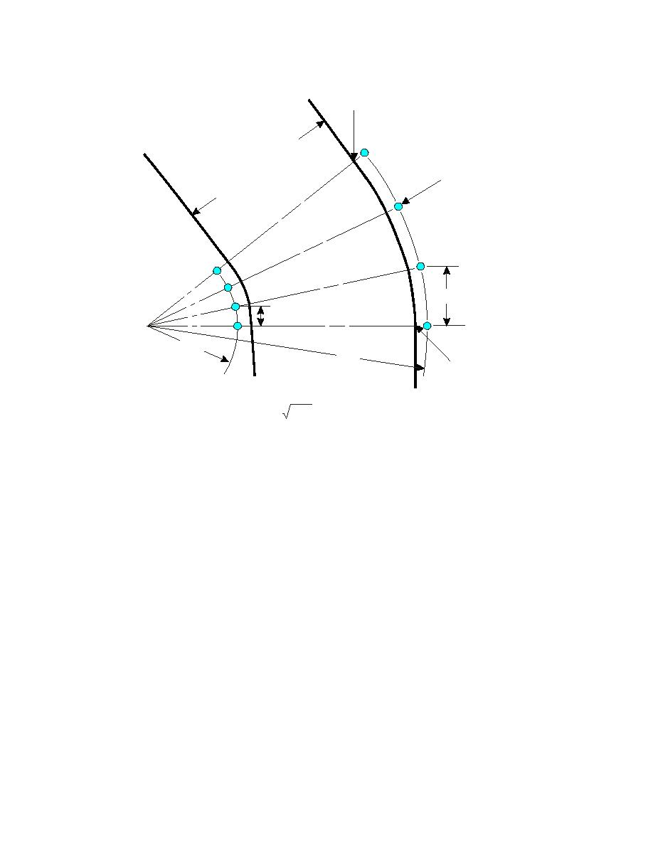
Figure 5-2. Taxiway Edge Lighting Configuration (Curves)
PT
Y
WA
I
AX
T
SEE NOTE 2
OF
S
E
ID
S
Z (CHORD)
SEE NOTE 1
Z1
R1
R2
PT
Z = 3.46
R
(APPROX.)
NOTES:
1. SPACE LIGHTS UNIFORMLY ON BOTH SIDES OF TAXIWAY
BETWEEN POINTS OF TANGENCY (PT). DETERMINE SPACING
BY DIVIDING TOTAL ARC INTO INCREMENTS Z. SELECTING NO
VALUE FOR Z WOULD CAUSE Z TO BE LESS THAN 6M (20FT)
1
(SEE TEXT).
2. ON ALL CURVES IN EXCESS OF 30 DEGREES OF ARC, USE A
MINIMUM OF THREE EDGE LIGHTS, INCLUDING THOSE AT PTs.
5-1.2.4
Entrance/Exit Lights
On intersections of taxiways with runways or aprons, place entrance/exit lights at the
point of tangency of the taxiway fillet with the runway or apron. Do not place them at an
intersection of taxiways. An entrance/exit light consists of 2 taxiway edge lights spaced
1.5 meters (5 feet) apart. One is located 1.5 meters (5 feet) out, on a line extending
through the first light and perpendicular to the side of the runway or apron. (See Figure
5-3.)
5-1.2.5
Apron Taxiways
For a taxiway that is adjacent to, or on the edge of, an apron, the taxiway edge lights
are usually placed only on the side of the taxiway furthest from the apron. ("Taxiing"
routes through an apron will not have these lights.)
78


 Previous Page
