UFC 3-535-01
17 November 2005
5-1.3
Tolerances
Adjust the longitudinal location of any light a maximum of 1.5 meters (5 feet) to avoid
installation problems. Move the companion light the same amount, if practical, to
maintain the relationship between them. Install taxiway edge lights within 0.15 meters (6
inches) laterally or longitudinally of the design location.
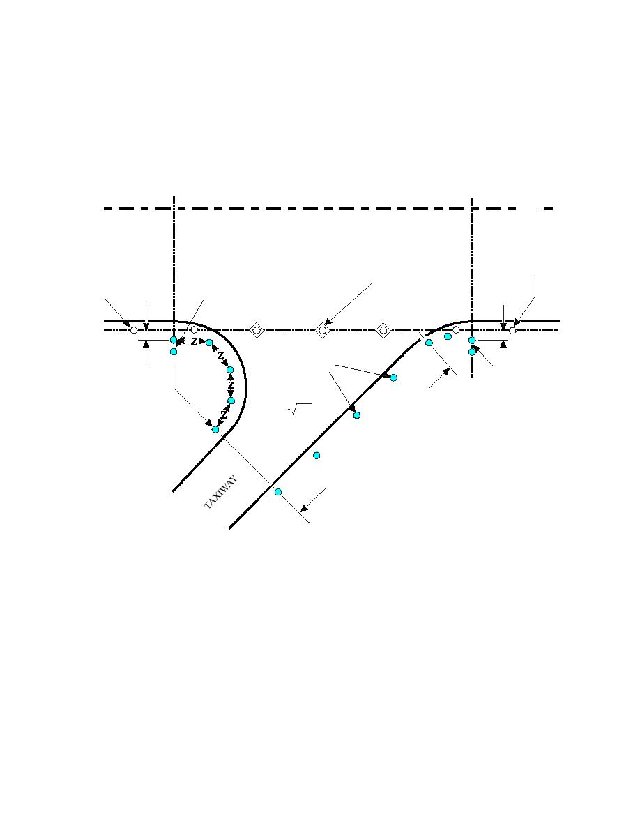
Figure 5-3. Taxiway Edge Lighting Configuration Entrance/Exit
C
L
RUNWAY
RUNWAY
EDGE LIGHT
IN-PAVEMENT RUNWAY EDGE LIGHT
ENTRANCE/
RUNWAY EDGE
0.6M (2FT)
EXIT LIGHTS
LIGHT
SEE NOTE 1
PT
PT
PT
TAXIWAY
EDGE LIGHTS
0.6M
ENTRANCE/
(2FT)
EXIT LIGHTS
N
IO
T
R
EC
Z = 3.46 R
S
(APPROX.)
T
H
IG
PT
A
R
ST
S
A
CE
A
SP
NOTES:
1. TAXIWAY LIGHTS MUST NOT BE IN LINE WITH RUNWAY EDGE LIGHTS.
2. PT = POINT OF TANGENCY
5-1.4
Photometric Requirements
Optimum aiming of lights depends on the design and output of the fixtures used in the
system. Taxiway edge lights must be omni-directional and emit aviation blue light with a
minimum intensity of 2 candelas from 0 to 6 degrees vertically and a minimum of 0.2
candelas at all other vertical angles.
5-1.5
Equipment
Use frangible mounted elevated fixtures in all areas, including Category II and Category
III operations, as noted below. Mount elevated fixtures a maximum of 0.35 meters (14
79


 Previous Page
