UFC 3-535-01
17 November 2005
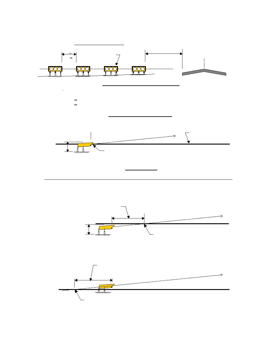
Figure 12-7. PAPI Positioning Guidance
4-box PAPI (FAA Type 880)
RW Edge
15M, +3 -0
9M, +.3
RW C
Light Housing
L
(50ft, +10, -0)
(30ft, +1)
Assembly (LHA)
horizontal
plane
PAPI is located so that center of lenses are level with RW centerline
at RRP (Runway Reference Point), within following tolerances:
+ 0.3M (1 ft) of RW elevation (lens or beam intercept plane with RW centerline at RRP
+ 25 mm (1 in) between LHAs (lens centers of one LHA with lens centers of another)
PAPI FRONT (APPROACH) VIEW
RRP
RW surface at
)
h (Glide Slope
Approach Pat
RW centerline
PAPI
2M (6 ft) max.
PAPI lens center elevation coincides with
RW centerline elevation at RRP
PAPI SIDE VIEW
ADJUSTMENTS TO PAPI LOCATION (see also paragraph 12.3.1.4)
A. When lens is below RW elevation at RRP.
Adjustment distance when PAPI LHAs
RRP
are lower than RW elevation at the RRP.
lide Slope)
pproach Path (G
PAPI A
2M (6 ft) max.
PAPI Approach Path coincides
with RW elevation at RRP
B. When lens is above RW elevation at RRP.
Adjustment distance when PAPI LHAs
are higher than RW elevation at the RRP.
lide Slope)
RRP
pproach Path (G
PAPI A
PAPI Approach Path coincides
with RW elevation at RRP
NOTE: See also paragraph 3.7.4 and Figure 3.16.
12-3.1.4.3 At locations where snow is likely to obscure the light beams, the light units
may be installed so the top of the unit is a maximum 2 meters (6 feet) above ground
175


 Previous Page
