TM 5-814-9
parallel to Range Road. Electrical and tele-
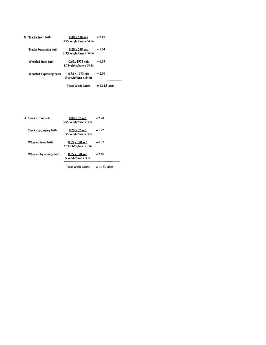
lanes required after a major training exercise:
phone lines also run parallel to this road. The
latrines can be tied into the sanitary sewer lines
which are within 0.75 miles (1.2 kilometers) of
the site. As long as wastewater from the facility
is recycled, the added load from the CVWF is
not expected to burden any of the existing
sewer lines.
A-3.
Engineering and design
a. Bath design. Figure A-3 shows the bath arrange-
ment for the new Fort Swampy CVWF consisting of
one tracked lane and two dual purpose lanes.
Dimensions are taken from the definitive drawings
and entrance and exit slopes are selected as shown.
The number of lanes required to meet the daily training exercise
Overall length is computed using these slopes.
is computed:
(1) Water cannons. The flow rate from the water
cannons in all lanes is selected as 80 gallons
per minute (gpm) (303 liters per minute). The
delivered pressure selected is 100 pounds per
square inch (psi) (6.8 atmospheres). These are
the maximum flow rate and pressure values
recommended and are chosen because the soil
consists of clays which are not easily removed.
(2) Flexors. Flexors in the dual-purpose lane
should be exposed 4 inches (10.1 centimeters)
with a center-to-center spacing of 17 inches
(43.2 centimeters), since about the same num-
ber of light- and heavy-wheeled vehicles are
Requirements for the Regular Army exceed those for the
expected to use the bath. The tracked lane
National Guard and because the installation is flexible in regard
should have flexors exposed 10 inches (25.4
to wash times, the designer selects 12 wash stations.
centimeters) and spaced 5.5 feet (1.7 meters)
o.c. because the primary user will be heavy
g. Site selection.
tracked vehicles.
(1) Geography. The site selected over several
(3) Entrance ramp. Because Fort Swampy does
possibilities is adjacent to the only main route,
not have freezing weather, the maximum slope
Range Road, that the vehicles will travel as
on the entrance ramp, 1 in 7, can be used. This
they return to the cantonment area from the
design will give a projected ramp length of
training fields.
24.5 feet (7.5 meters).
(2) Geology. The site has 45 feet (13.7 meters) of
(4) Exit ramp. The maximum slope of 1 in 11 can
relief over a 25-acre (0.10-square kilometer)
be used for the exit ramp. With this slope, the
area. The site is on the top of a ridge that is
projected ramp length is 38.5 feet (11.7
approximately 200 feet (61 .0 meters) wide
meters).
and 700 feet (213.4 meters) long. Site borings
have shown that the water table will not inter-
b. Wash station design. The flow rate selected per
fere with construction or operation of the
hose is 30 gpm (114 liters per minute) at 90 psi
CVWF. The site has never been used for any
(6.1 atmospheres) pressure. These are the
purpose. Engineers have determined that if
maximum flow rate and pressure values
work to lengthen or widen the ridge is to be
recommended and were chosen because the soil
done at the site, it will raise construction costs
consists of clays which are not easily removed.
considerably due to the location of the bedrock.
Interior washing points, which are low-pressure,
Figure A-2 shows a topographic map of the
low-flow outlets consisting of yard hydrant and
site.
utility hose will be placed at each island. The
limited area for construction on the natural ridge
(3) Utilities. All required utilities are within a
will dictate the configuration of the wash station
reasonable distance to the proposed site. A 10
area. Two configurations, A and B, are evaluated.
inch (25.4-centimeter) potable water line runs
A-6


 Previous Page
