TM 5-628/AFR 91-44
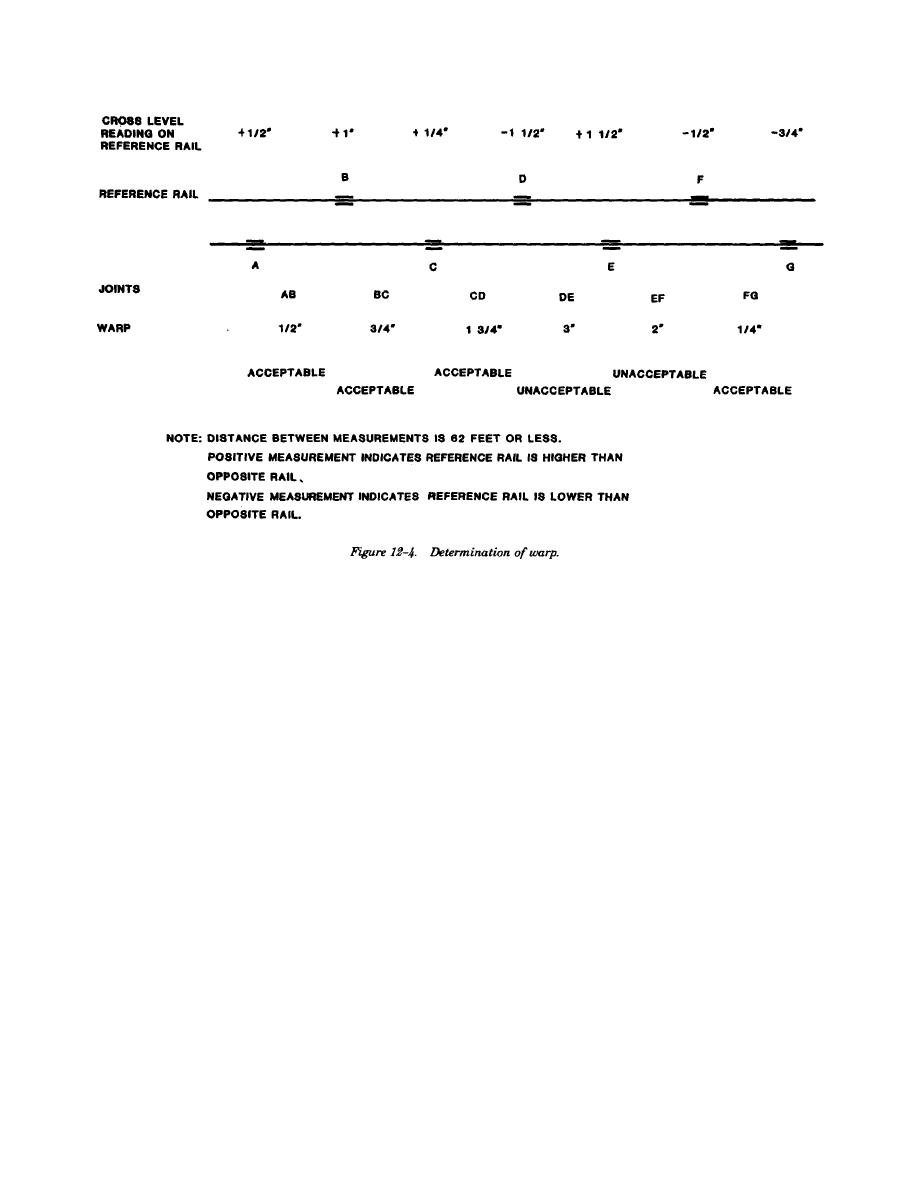
b. Designated warp. The designated warp on
(0.625) inch below the top of the rail head. The
both tangent and curved track is zero.
alinement measurement is the distance in inches
c. Allowable deviations and operating restric-
from the midpoint of the stringline to the gage side
tions.
of the line rail. It is measured at right angles to the
(1) At any location where the warp exceeds
stringline.
c. Designated alinement. For tangent track the
1 (1.75) inches, operations shall not exceed 10
mph.
designated alinement is zero. For curved track the
(2) At any location where the warp exceeds
designated alinement is the degree of curvature. In
2 (2.50) inches, operations shall not exceed 5
spirals the change in curvature will be at a uniform
mph.
rate.
d. Curvature measurement. On curves, 1 inch
(3) Operations shall not be permitted over
any location where the measured warp is greater
distance from the stringline to the line rail equals
than 3 (3.00) inches.
approximately 1 degree of curvature, as shown in
figure 12-5. If the degree of curvature is not
known, it can be determined as follows:
12-6. Alinement.
(1) Beginning at a point near the center of
a. Definition. Alinement is the relative position
the curve, mark at least two stations spaced 31 feet
of the rails in a horizontal plane.
apart in both directions along the line rail.
b. Measurement. Alinement is measured at the
midpoint of a 62-foot stringline stretched along the
gage side of the line rail at a distance of %
12-4


 Previous Page
