TM 5-628/AFR 91-44
CHAPTER 12
TRACK GEOMETRY
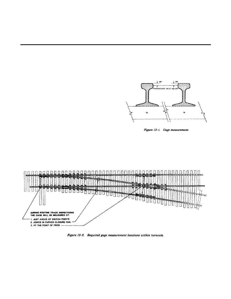
plane % (0.625) inch below the top surface of the
2-1. General.
rail head, as shown in figure 12-1. Gage measure-
a. One rail shall be designated as the line rail.
ments shall include any evidence of lateral move-
The alignment of the track is established by this
ment under load.
rail. Either rail may be used as the line rail on
tangent track so long as the same rail is used for
the entire length of the tangent. The outside rail in
a curve is always the line rail.
b. In curves, the inside rail is designated as the
grade rail. The grade rail is the reference from
which superelevation is applied to the outside rail
of the curve.
c. During routine track inspections, track
geometry measurements shall be taken as a
minimum at the following locations:
(1) Wherever there are visual indications of
track geometry deviations.
(2) Wherever track geometry deviations
were previously detected, unless the deviation has
been corrected.
b. Measurement locations. During routine
(3) Other locations as specified in this
track inspections gage shall be measured at the
chapter.
following locations:
(1) In turnouts, just ahead of switch points.
12-2. Gage.
(See fig 12-2)
a. Definition. Gage is the distance between the
two rails, measured at right angles to the rails in a
(2) In turnouts, at the joints in curved
(5) Wherever wear marks on a tie indicate
closure rails. (See fig 12--2)
lateral tie plate movement.
(3) At the point of frog on both sides of
(6) At locations where ties are badly
turnouts and rail crossings. (See fig 12-2)
skewed.
(4) Wherever there is a dark streak running
(7) In road crossings.
along the field side of the top surface of the rail
(8) In extremely sharp curves (12 degrees or
head.
greater) gage shall be measured in at least three
well-spaced locations within the curve.
12-1


 Previous Page
