TM 5-805-4/AFJMAN 32-1090
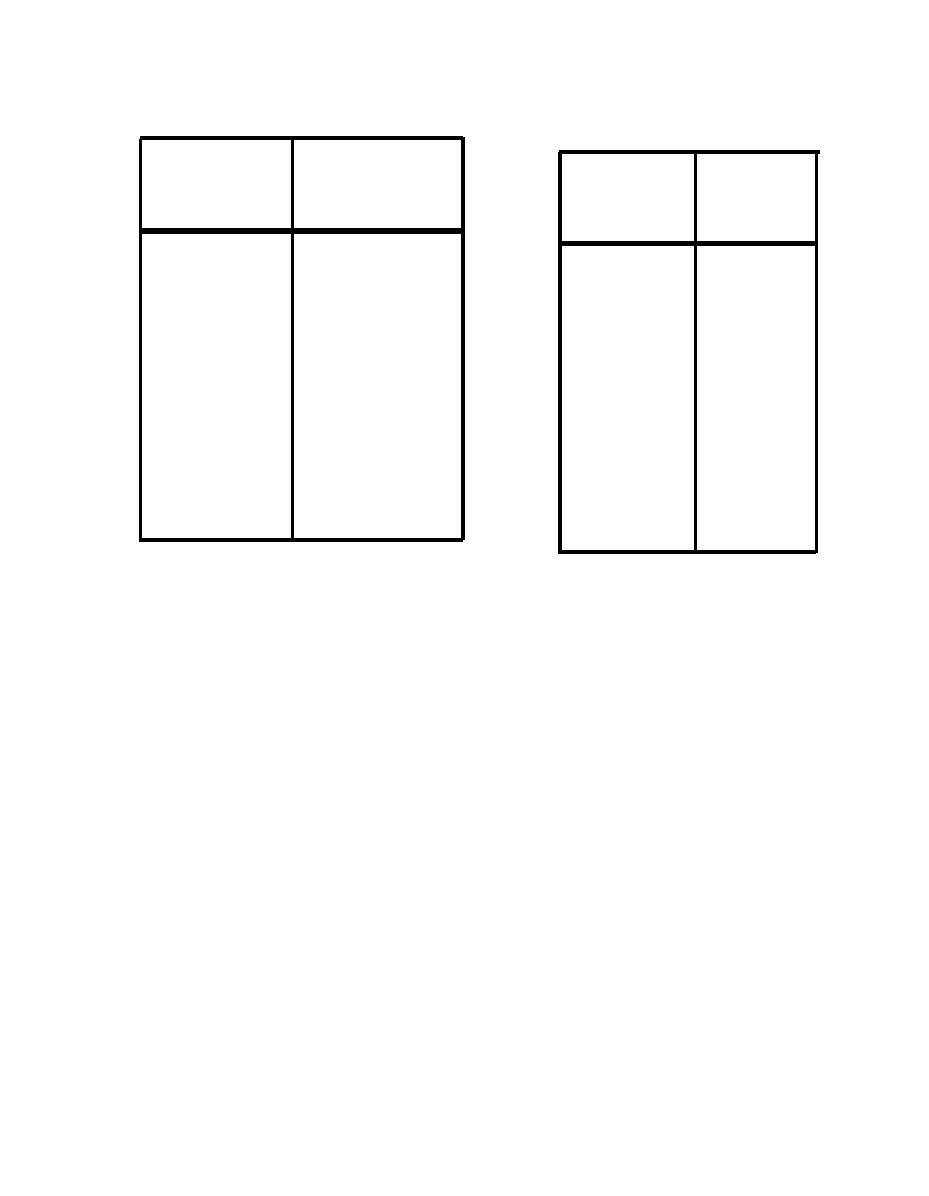
Table C-5. Sound Pressure Levels (in dB at 3-ft. Distance From
Table C-6. Sound Pressure Levels (in dB at 3-ft. Distance) for
the Front) for Boilers.
High-Pressure Thermally Insulated Steam Valves and Nearby
Piping.
Octave
Sound Pressure
Octave
Sound
Level, dB
Pressure
Band
Level
5 0 - 2 0 0 0 BHP
(Hz)
(Hz)
(dB)
90
31
70
31
90
63
70
63
90
125
70
125
87
250
70
250
84
500
75
500
82
1000
80
1000
80
2000
85
2000
76
4000
90
4000
70
8000
90
8000
88
A-weighted,
A-weighted,
dB(A)
94
dB(A)
desirable to obtain from the manufacturer actual
be expressed in different ways: sq. ft. of heating
measured noise levels for all directions of interest,
surface, BTU/hour, lb of steam/hour, or bhp boiler
but if these data are not forthcoming, it is essen-
horsepower). To a first approximation, some of
tial to be able to approximate the directional
these terms are interrelated as follows:
pattern of the cooling tower noise. For aid in
33,500 BTU/hour = 1 bhp
identification, four general types of cooling towers
33 lb of steam/hour = 1 bhp.
are sketched in figure C-3: A.) The centrifugal-fan
In the manual, all ratings have been reduced to
blow-through type; B.) The axial-flow blow-through
equivalent bhp.
type (with the fan or fans located on a side wall);
C.) The induced-draft propeller type; and D.) The
C-9. Steam Valves
"underflow" forced draft propeller type (with the
Estimated noise levels are given in table C-6 for a
fan located under the assembly).
a. Sound power level data. Sound power level
typical thermally insulated steam pipe and valve.
d a t a are given for both propeller-type and
Even though the noise is generated near the
centrigual-fan cooling towers.
orifice of the valve, the pipes on either side of the
(1) Propeller-type cooling tower. The approxi-
valve radiate a large part of the total noise energy
mate overall and A-weighted sound power levels of
that is radiated. Hence, the pipe is considered,
propeller-type cooling towers are given by equa-
along with the valve, as a part of the noise source.
tions C-1 and C-2, respectively: for overall PWL
Valve noise is largely determined by valve type
(propeller-type),
and design, pressure and flow conditions, and pipe
Lw = 95 + 10 log (fan hp),
(eq C-1)
wall thickness. Some valve manufacturers can
and for A-weighted PWL,
provide valve noise estimated for their products.
(eq C-2)
Lwa = 86 + 10 log (fan hp),
C-10. Cooling Towers and Evaporative Con-
w h e r e "fan hp" is the nameplate horsepower
densers.
rating of the motor that drives the fan. Octave
band PWLs can be obtained by subtracting the
The generalizations drawn here may not apply
values of table C-7 from the overall PWL.
exactly to all cooling towers and condensers, but
(2) Centrifugal fan cooling tower. The approxi-
the data are useful for laying out cooling towers
mate overall and A-weighted sound power levels of
and their possible noise control treatments. It is
C-5


 Previous Page
