EXAMPLE DESIGNS
DG 1110-3-112 May 1979
6-3 EXAMPLE DESIGN-SCHEME A-1 FOR 6,000 MILITARY STRENGTH
a. SITUATION. The requirements of this project are similar to those for Scheme A. However, in this
case, the installation is located in an area that is subject to more severe weather conditions,
particularly in the winter. The site, which is immediately adjacent to the Main Library, is very small and
narrow, with limited space for development of parking facilities. However, the parking spaces available
on the library site can be shared with the ACES Center given proper access provided by good site
planning.
b. PLANNING. The authorized space allowance and staffing, and the enrollment and usage of the
ACES Center are the same as determined in Scheme A. The space requirements are the same as
those indicated in Table 6-8.
c. DESIGN SOLUTION.
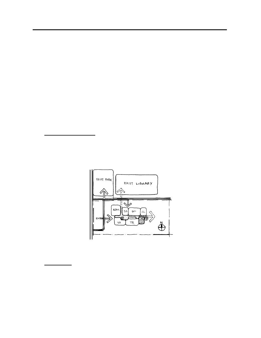
(1) Basic Spatial Organization. This ACES Center, basically organized as a simple linear/modified
axial scheme, is dictated by the configuration of the site. Due to the limited site area and the space
requirements of the program, a two-story scheme is necessary. The two-story configuration also helps
conserve energy by exposing less building surface to the elements. An axis perpendicular to the main
linear axis is desired to connect the new ACES facility to the existing library as shown in Figure 6-3.
Figure 6-3 Basic Spatial Organization-Scheme A-1
(2) Example Plan. Staff and support spaces are located near the main and service entrances on
the ground level as shown in Figure 6-4. Academic spaces are located on two floors with classroom,
lecture room, MOS library and self-paced learning room located on the second floor, linked to the
existing library. The 750 SF module again forms the basic layout system in this example solution.
6-10


 Previous Page
